Fenley patent
A design that has perhaps some similarities with the SEM fusor, see: https://patentimages.storage.googleapis.com/aa/28/41/7214e0b51beb9f/US10354761.pdf
Part of the text and all images in this page come from this patent.
Systems and methods are disclosed herein relating to fusion reactors for fusing
particles via multiple periodic collisions.
A fusion reactor may include a first evacuated region, such as a chamber, with a
plurality of charged particles therein.
A uniform magnetic field may be applied to the region to radially confine moving
charged particles within the region by inducing circular trajectories
Upper and lower electrodes may be positioned on ends of the region to
axially confine charged particles within the region.
An energizing beam may be pulsed at a cyclotron frequency corresponding to the
mass and charge
of the particles to cause oscillating periodic collisions of the particles
along the beam path
as the particles travel in the circular trajectories with increased velocity
after each pulse of the energizing beam.
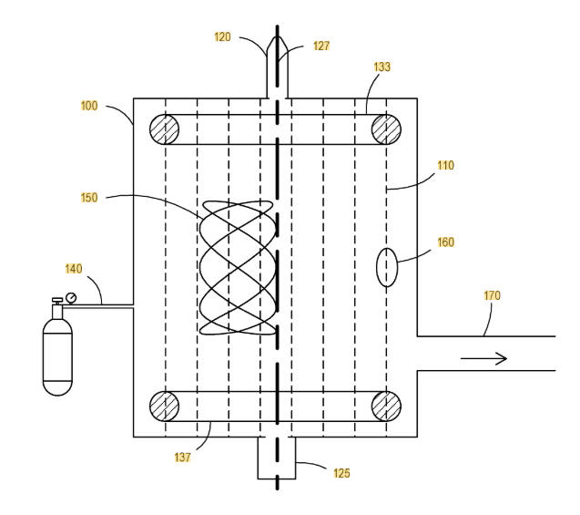
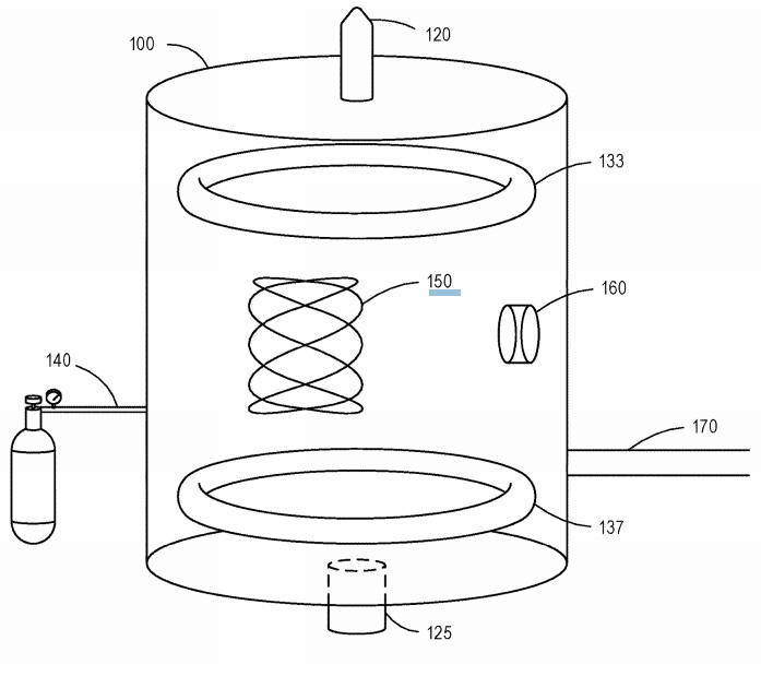
Fig. 1a A side view of a reactor device and example ion paths, according to one embodiment
150 = example of ion path
100 = vacuum vessel or evacuated chamber (any
difference between the two?)
110 = uniform magnetic field, where the magnetic field traverses the
chamber/vessel axiallly (so the magnetic field
is vertical, in fig. 1a, must it be uniform?)
140 = fuel is introduced at low concentration by means of a gas
delivery system
120/127 = a periodic energizing beam source is pulsed down the focus
of the device at the cyclotron frequency.
Molecules of the fuel substance in the energizing beam path 127 are bombarged
with high energy electrons, photons, ions, or the like
(quite general..)
and consequently become ionized and energized.
125 = energy from the energizing beam that is not transferred to the fuel is
recovered by an energy beam recovery system
(okay, but how?).
150 = each fuel ion that is hit by the energizing beam
(a fuel molecule is hit by the beam and split
into a ion and an electron?)
is held in a stable energetic ion path, or orbit, as shown by the
example ion path.
( Do the ions not interact with other ions, changing of speed and
velocity, and so getting all kind of velocities?
An fuel molecule is hit by the beam (in the centre
line) and split into a positive ion and an electron. The ion will get
extra velocity/speed.
Now only regard the component of the velocity in a horizontal plan. The
magnetic field is perpendicular to this component of the velocity,
as is the Lorentz force. In this horizontal plane this ion will move in circles,
and indeed will come back to the centre
line.
If an ion only increases (or in general, changes) its speed/velocity in
the centre line, it will always come back to the centre line.
But.. if it encounters some interaction (collision) outside the centre line, it
will not come back to the centre line..... I am afraid this could be quite a
flaw in this design :(
Or the amount of fuel (ions) is made very small, and then also the, possible, energy output would probably be very small.
The energy beam will mainly give energy (velocity)
to the ions in the vertical direction, I suppose.
Because the direction of the energy beam is in the vertical direction.
But some ions will gain speed/velocity in the x-y direction (perpendical to the
vertical axis).
Equation 1: f = q.B / (2πm) q= charge of particle (coulomb) , B= magnetic field strength (tesla), m = mass of particle
Because the cyclotron frequency is independent of the velocity and the radius of the particle trajectory, the cyclotron frequency is also independent of the kinetic energy of the particles.
Should any ions spilar too far from the center of the chamber 100
(above or down under) , positively
chaged end containment electrodes,
including upper electrode 133 and bottom electrode 137, will repel them back
toward the center, thereby restricting the axial range of motion of the ions
150.
In some embodiments, any ions that are not at the focus of the energizing
beam 127 at the time of the energizing beam pulse will have their stable orbit
pertubed
by a stray particle or ion removal electrode 160 that is charged,
periodically, in sync with the energizing beam (but the
electrical field of the removal electrode will pertube all ions??)
These gray ions will gradually drift toward the walls of the chamber
100 where they can be removed by, for example, a vacuum system 170.
Fig. 1b A perspective view of the reactor device with example ion paths, according to one embodiment.
Discussion about this in fusor.net:
https://fusor.net/board/viewtopic.php?f=14&t=11281&start=10
Fig. 1c A top view of the reactor chamber 100 with example ion trajectories151, according to one embodiment.
As illustrated, each ion path (represented by dashed circles) eventually
contacts a central focus point that is within the path of the
energizing beam. Thus, energetic fuel ion trajectories 151 periodically
pass through the focus (e.g. axis) of the chamber because the fuel particles
were ionized at the center of the device by the pulsed beam.
I would say, the ions contacts a central focus line (the central vertical line).
But what happens if the energy beam is not pulsed,
but contant? We still get ions that gain speed/velocity and will follow
paths 150, I suppose (a constant beam is mentioned in the patent).
Fig. 2. A simplified diagram of an uniform field 210 within an evacuated chamber 200, according to one embodiment. As illustrated the evacuated chamber 200 may include an upper confining electrode 233 and a lower confining electrode 237.
What is the purpose of these upper and lower confining electrodes? I suppose these are the rings of fig. 1.
In the SEM fusor D+ ions could be injected along the
centre axis. These ions can exchange energy with the ions that are already in
the vacuum chamber,
a bit similar as the energy beam of this patent.
Some more images from the patent:
Fig. 3a Exploded view of a simplified
diagram of a single reactor.
320 = with a beam source
300 = evacuated chamber
335, 336 = confinement electrodes
325 = beam recovery collector, according to one embodiment
The beam source may transmit pulses of electromagnetic energy or an
electron beam at the cyclotron frequency (or
continuously in some embodiments). Each of the confining electrodes
and the chamber may have a physical aperture or electromagnetically
transparent (at the relevant frequences) aperture for the energizing
beam to pass axially through to the beam energy recovery collector 325.